
A Guide to Die-Casting Technology
Die-casting allows the production of near-net-shape parts in large series at relatively low costs and benefits from a high degree of automation of the production sites. It is dedicated to transforming parts made of non-ferrous alloys (aluminium, zinc, copper, magnesium, etc.) for various markets (automotive, household appliances, construction, etc.). The worldwide expansion of the automobile industry has contributed to the continuous increase in the tonnage of injected aluminium alloys.
The principle of the technology
Die-casting consists of injecting the liquid alloy at high speed (40 to 60 m/s at the pouring chemical attacks) into a steel mould (made of X38 CrMoV5) and applying a very high pressure (80 to 100 MPa) during the whole solidification process. Injection moulding machines vary significantly in size, from 100 tons (injection of small multi-cavity Zamak parts) to 2500 tons (or more) for engine blocks or large aluminium automotive mechanism housings. The technology is relatively standardised, which means that a mould can be transferred from one machine to another without major adaptation (depending on the availability of work sites).
Manufacturing parameters
On traditional machines, the injection process is divided into 3 phases. At a slow speed, the first phase allows the metal to be brought to the pouring attack. The second phase, at high speed, fills the cavity. Finally, the third phase is triggered after the filling. It is a compression phase at very high pressure, which allows to fill the shrinkage of the metal during the solidification and to strongly compress the porosities (blowholes, shrinkage) in part. On recent machines, up to twenty phases can be programmed if necessary to control the injection more finely with variations in piston speed during the filling phase and pressure changes during the compression phase or, finally, braking of the piston at the end of filling.
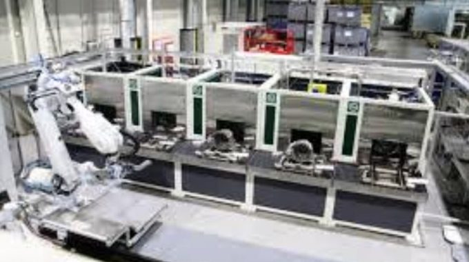
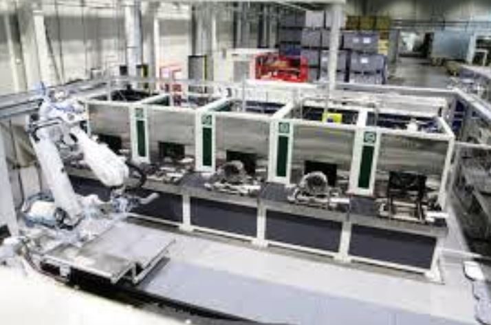
On all injection presses, the high speed or high-pressure phases take advantage of a potential energy reserve (nitrogen cylinder at 150-200 bars) transformed via an accumulator into a water/glycol pressure. The low-speed movements (machine opening, ejection, low speed of the piston, …) are, on the other hand, activated directly by the hydraulic unit of the machine. Once the sprue is ejected, the mould surface is cooled, and a lubricating agent is applied (useful for demoulding the sprue). The relatively short cycle time – from a few tens of seconds (small parts) to more than a minute and a half (for large amounts) – can only be achieved by automating all the operations of the process (automatic ladle, part pick-up by robot, automated poteyage operation, automatic degreasing on vertical press).
The injection mould
The injection mould for die casting is relatively complex and expensive. It can represent 10% to 15% of the part price. This initial tooling cost requires a minimum economic series (20,000 to 40,000 pieces) to be profitable. It limits de facto die casting to large series. The mould, which can be multi-cavity, includes a fixed and a mobile part and, most often, lateral drawers to allow the manufacturing of non-demoldable part areas. The mould cavity – in contact with the liquid alloy – is made of hot-forged steel (X38CrMoV5 or H11), which is heat-treated (one quenching and two tempering operations) and may be subject to surface treatments (nitriding, etc.). The carcass, which contains the cavity, is made of less noble steel and can be reused several times.
An ejection system (battery, ejector, ejection cylinder, etc.) in the moving part of the mould allows the cluster to be ejected. Water cooling channels cool the moulds, and temperature regulated on large moulds by thermoregulation circuits (oil or water). The parts feeding system is composed of the casting gates, the feeding arms and the main channel connected to the pellet (aluminium) or the sprue (Zamak). The design of the moulds increasingly uses numerical simulation (filling/solidification) upstream of the manufacturing process to optimize the quality of the parts.
Advantages and limitations of die casting
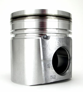
Die casting has many advantages. First of all, it allows the production of exact parts (near-net-shape) and low thickness, requiring less subsequent machining than with other casting processes (sand casting, gravity die casting). The productivity of the production sites is generally very good with one operator for two or 3 machines) in the Western countries. On the other hand, the internal health level is usually less good than sand or shell moulding (for an equivalent part geometry) due to gaseous porosities trapped during the filling process. These porosities prevent heat treatment. Moreover, die-casting does not allow the positioning of destructible sand cores and, therefore, the realization of non-demoldable hollow zones as with other casting processes. Finally, the diversity of available alloys is much more limited than in gravity casting.
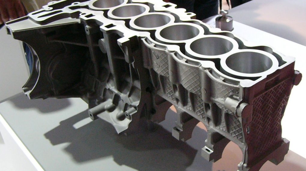
Parts in die casting
The emblematic parts of aluminium die casting are the engine crankcase (4 or 3 cylinders with over-moulded cast iron liners), the clutch housing, the oil pan, the steering column, etc. The steering wheel armatures, formerly made of aluminium (overmolded on an iron armature), are nowadays mostly injected in monobloc magnesium to limit the weight and the moment of inertia. Brass pressure die castings are used for gearbox forks, water meter bodies and new markets (copper cage rotor, antibacterial alloy parts for the medical world). Zinc alloys are used in a much more comprehensive range of needs than aluminium alloys, including the automotive, electronics (covers, card fasteners), luxury goods (perfume stoppers, etc.), sports, and medical sectors. Finally, lead alloys are used in fishing, radioprotection, and counterweights.
The different machines (cold room, hot room, …)
Depending on the alloys processed, either cold room or hot room machine technology is used. These two technologies differ in terms of the holding furnace. In cold chamber casting, the liquid metal is taken by an automatic ladle (or by a dosing furnace), poured into a metal container and injected by a horizontal injection piston. The injection system is immersed in the liquid metal (at 400°C). A vertical injection piston injects the metal, passing through a gooseneck and an injection nozzle into the mould. This technology, reserved for zinc and lead alloys (less aggressive than aluminium for metal elements), leads to shorter cycle times but does not allow multiplication pressures (3rd phase) as strong as with cold chamber technology.
There are also hot chamber machines called “multi-slide” and injection in the parting line. These machines (Dynacast, Techmire), with very high productivity, are reserved to inject minimal parts (a few tens of grams) in zinc, lead, or magnesium alloy. The machine has two or four slides on which the different blocks that make up the mould are mounted. As this technology is specific, the mould is not compatible with traditional hot chamber die casting machines.
Quality control of the parts
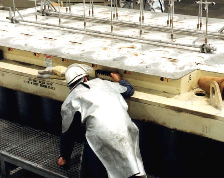
The parts are, first of all, 100% visually checked by an operator who monitors the machine to identify any external defects (re-casting, no-shows, cracks). Then, parts are regularly taken from each shift (frequency depending on the criticality of the product) and are inspected by X-ray to detect internal defects (mainly blowholes and shrinkage) that are not acceptable according to the specifications of the part. In some cases, an air/water tightness check can be performed by sampling, or an air/airtightness check can be performed automatically after machining. Leaky parts can be impregnated with a resin that infiltrates the open pores to fill them. A portion of the components can be recovered after this impregnation operation. In order to avoid controlling the parts individually, the manufacturing parameters are increasingly controlled as completely as possible. Thus, on particular sites, the machine’s major injection parameters are monitored at each cycle, which can discard the parts in real-time if one of the monitored parameters leaves a min-max control interval. The rejected parts are then either scrapped or 100% NDT controlled.
The short history of die-casting
The important development of the printing industry around 1850 made it necessary to produce lead-tin typefaces (previously made individually and by hand) in large quantities and at a low cost. It strongly contributed to the development of the first manual injection machines dedicated to this market. Then the die casting developed with the first applications in the bicycle and phonograph industry in the USA. In 1868, Charles Babbage (Great Britain) produced small precision parts (lead, antimony, tin and zinc) for his mechanical computer project. Then, Hermann Doehler founded the Doehler Die Casting Company in 1908 in Brooklyn (New York) and worked a lot to develop the technology (mould, machine, …). Then, the First World War oriented the die casting towards military applications (grenades, rockets, ..). No zinc alloy composition was then standardized; the alloy can vary significantly from one workshop to another. After the Second World War, the development of the automobile in the USA and the “chrome zinc” design, which was very fashionable at the time, launched the mass production of zinc casting.
The development of cold room machines for aluminium came much later and only commercially in the 1930s. One of the pioneers in Europe was the Czech Josef Polak with vertical piston cold chamber machines (some of them are still in operation in Eastern Europe). Then the horizontal injection of aluminium, more straightforward, became widespread with the mechanization and progressive automation of the sites (ladle and automatic post, …) until today’s machines. Compared to other industrial processes, die-casting was robotized very early, as the very first industrial robot, developed by Unimation Inc., was used in the General Motors Ewing Township plant (Trenton/USA) in 1961 to extract automotive parts from a die-casting cell to limit the workload and to gain in cycle time.
Alloys processed in die-casting
Secondary aluminium alloys (from recycling) are by far the most used in die casting. AlSi9Cu3(Fe) (or 46000 according to the European standard EN 1706) is the leading alloy in the world. It is known under different names (A380 in North America, ADC10 in Japan, …) quite similar in its chemical composition. Then there are AlSi12 (eutectic) and AlSi12Cu, AlSi10Mg or the hypersilicon AlSi17Cu4 alloys, which are less used. Finally, new ductile low iron alloys (Silafont type) are coming on the market to produce parts with high mechanical properties (with or without heat treatment).
How did you find this post? Please, remember to share your comments below.
Read more here: